Wire drawing operation
Wire drawing is a metalworking operation used to reduce the cross-section of a wire by pulling the wire through one or more dies. There are many applications for wire drawing, including electrical wiring, cables, tension-loaded structural components, springs, paper clips, spokes for wheels, and stringed musical instruments. Although similar in operation, drawing is different from extrusion, because in drawing the wire is pulled, rather than pushed, through the die. Drawing is usually performed at room temperature, thus classified as a cold working operation, but it may be performed at elevated temperatures for large wires to reduce forces.
Process
The wire drawing process is quite simple in concept. The wire is prepared by shrinking the beginning of it, by hammering, filing, rolling, or swaging, so that it will fit through the die; the wire is then pulled through the die. As the wire is pulled through the die, its volume remains the same, so as the diameter decreases, the length increases. Usually, the
wire will require more than one draw, through successively smaller dies, to reach the desired size. This can be done on a small with a draw plate, or on a large commercial scale using automated machinery. The operation of wire drawing changes material properties due to cold working.
The area reduction in small wires is generally 15–25% and in larger wires is 20–45%. The exact die sequence for a particular job is a function of area reduction, input wire size, and output wire size. As the area reduction changes, so does the die sequence.
Commercial wire drawing usually starts with a coil of hot rolled 9 mm (0.35 in) diameter wire. The surface is first treated to remove scales. It is then fed into a wire drawing machine which may have one or more blocks in series.
Single block wire drawing machines include means for holding the dies accurately in position and for drawing the wire steadily through the holes. The usual design consists of a cast-iron bench or table having a bracket standing up to hold the die, and a vertical drum which rotates and by coiling the wire around its surface pulls it through the die, the coil of wire being stored upon another drum or “swift” which lies behind the die and reels off the wire as fast as required. The wire drum or “block” is provided with means for rapidly coupling or uncoupling it to its vertical shaft, so that the motion of the wire may be stopped or started instantly. The block is also tapered, so that the coil of wire may be easily slipped off upwards when finished. Before the wire can be attached to the block, a sufficient length of it must be pulled through the die; this is effected by a pair of gripping pincers on the end of a chain which is wound around a revolving drum, so drawing the wire until enough can be coiled two or three times on the block, where the end is secured by a small screw clamp or vice. When the wire is on the block, it is set in motion and the wire is drawn steadily through the die; it is very important that the block rotates evenly and that it runs true and pulls the wire at a constant velocity, otherwise “snatching” occurs which will weaken or even break the wire. The speeds at which wire is drawn vary greatly, according to the material and the amount of reduction.
Machines with continuous blocks differ from single-block machines by having a series of dies through which the wire is drawn in a continuous fashion. Due to the elongation and slips, the speed of the wire changes after each successive redraw. This increased speed is accommodated by having a different rotation speed for each block. One of these machines may contain 3 to 12 dies. The operation of threading the wire through all the dies and around the blocks is termed “stringing-up”. The arrangements for lubrication include a pump that floods the dies, and in many cases also the bottom portions of the blocks run in lubricant.
Often intermediate anneals are required to counter the effects of cold working, and to allow further drawing. A final anneal may also be used on the finished product to maximize ductility and electrical conductivity.
Lubrication
Lubrication in the drawing operation is essential for maintaining a good surface finish and long die life. The following are different methods of lubrication:
- Wet drawing: the dies and wire or rod are completely immersed in lubricants
- Dry drawing: the wire or rod passes through a container of lubricant which coats the surface of the wire or rod
- Metal coating: the wire or rod is coated with a soft metal which acts as a solid lubricant
- Ultrasonic vibration: the dies and mandrels are vibrated, which helps to reduce forces and allow larger reductions per pass
- Roller die Drawing (also referred to as Roll drawing): roller dies are used instead of fixed dies to convert shear friction to rolling friction with a dramatic reduction in the drawing forces as reported by Lambiase. When roller dies are adopted, the drawing stages are composed of 2-4 idle rolls, and the wire is pulled within the roll clearance. This type of solution can be easily adopted also to produce flat or profiled drawn wires.
Various lubricants, such as oil, are employed. Another lubrication method is to immerse the wire in a copper(II) sulfate solution, such that a film of copper is deposited which forms a kind of lubricant. In some classes of wire, the copper is left after the final drawing to serve as a preventive of rust or to allow easy soldering. The best example of copper-coated wire is in MIG wire used in welding.
Wire drawing operation
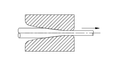
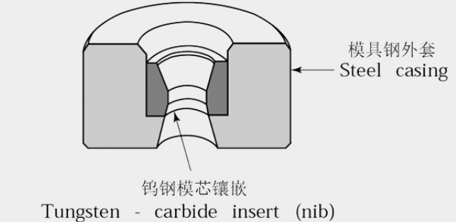
Wire drawing is a steady-state, cold-forming operation in which a rod or wire is pulled or drawn through a single die or a series of consecutive dies. Each die and the subsequent dies have diameters that are smaller than that of the input material, and the cross-sectional area of the wire is reduced as it passes through each die. Theoretically, wire drawing is a “chipless process” in which no material is intended to be removed. Because of this, the volume of the wire essentially remains the same as it is drawn, but the length of the wire increases, or elongates, according to its new diameter. In practice, some metal fine generation occurs, depending on the material being drawn and lubrication conditions.
The wire drawing process is said to be cold because heat is not applied to aid in the metal forming. During drawing, the input material properties change due to cold working, and the temperature does rise, often dramatically, as the wire is drawn down to smaller diameters.
In the wire drawing operation, the machines used are single, but more often, multiple die (multiple draft or tandem) devices that are designed to draw one or more wire(s) at a time. As the rod or wire is pulled through each die, the diameter is reduced (area reduction) and the length is increased (elongation).
In wire drawing machines, pulling of the material to be drawn is done by driven capstans. On a single draft machine, only one capstan exists, and multiple draft machines will usually have the number of capstans equal to the number of drafts. The capstans can be arranged in-line (tandem) where each capstan is driven by a single shaft or in a cone-type arrangement where more than one capstan is on the same shaft. The key parameters in wire drawing are area reduction, wire elongation, and slip


